Waveguide Technology
Although Fibre-Lyte is simple and elegant in concept it is extremely powerful in performance.
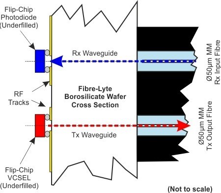
The Fibre-Lyte OSA is mounted on a Borosilicate carrier. The OSA optoelectronic devices are flip chipped to the carrier using tracks which have been metallised on to the carrier's top surface. The track dimensions and layouts have been fully simulated so that the RF performance is optimised giving highest BER performance and signal integrity even at 25Gbps.
The optical signals exit and enter the OSA by means of waveguides processed into the Borosilicate carrier.
Fibre-Lyte does not use lenses so the optical interface is always clean and flat with nowhere for dirt to hide.
Electronic Interfacing
This could not be easier.
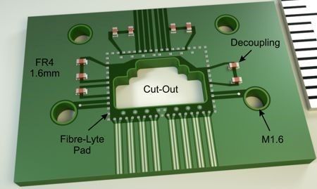
The OSA can be mounted into any appropriate printed circuit board by means of a standard LGA interface. The OSA can be solder reflowed using standard reflow solder techniques.
The image right shows a PCB with land and cut out ready for Fibre-Lyte soldering.
.
Flex Attachment
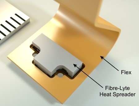
However, Fibre-Lyte can also be mounted on to a flexible printed circuit
This configuration can be used for applications which present challenging mechanical mounting.
Optical Interfacing
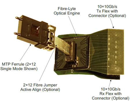
The optical interface is easily accommodated by means of actively aligning a butt coupled fibre ribbon or MT ferrule to the lower surface of the carrier.
A 90 degree bending mechanism can be accommodated.
The image right shows a fibre jumper aligned and bonded to Fibre-Lyte.